Everything under Control
A free application note on the design of motor control systems as a multi-disciplinary problem, covering mechanical, electrical and control systems.
The design of motor control systems is a multi-disciplinary problem, as it contains mechanical, electrical and control systems. This application shows how Optimus is used with Simulink to modify the motor pole width and the excitation signal, in order to optimize torque ripple and switching loss. Optimus explores the entire design space and automatically improves the design using its powerful optimization algorithms without any user intervention.
Simulation facts
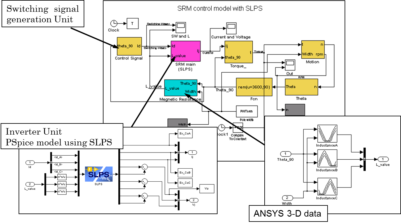
The motor control system is modeled with Simulink. The motor’s electromagnetic field with different pole width is simulated by ANSYS in advance, and the resulting coil inductance values are imported into the Simulink model. The inverter circuit is modeled by PSpice, with SLPS as an interface to the Simulink model.
Those motor control system evaluations are open-ended solutions that state how a given design performs - not what the design should be to meet a target performance. If the objective is to optimize the motor control system, Optimus is needed to explore the entire design space, to provide deeper engineering insights and to identify designs that meet or even exceed design specifications.
Solution approach
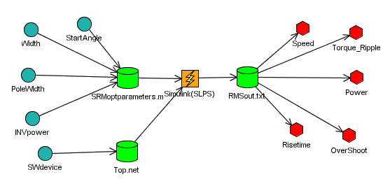
The entire simulation workflow is captured using the Optimus graphical user interface. This workflow includes all simulation codes, as well as the related input and output files. The engineer selects the input parameters and responses which are required for optimization, from the automatically generated parameter list. Optimus parameterizes the input file and parses the output file for the desired combination of output parameters, allowing for an automated execution of the simulation workflow.
TO FIND OUT MORE, DOWNLOAD YOUR COPY!
Download your copy »©2026 Noesis Solutions • Use of this website is subject to our legal disclaimer
Cookie policy • Cookie Settings • Privacy Notice • Design & Development by Zenjoy